Why Antenna Geometry Decides How Well Your Signal Actually Travels
A practical look at how gain, impedance matching, polarization and bandwidth in antenna design shape real-world signal performance.
A radio can have a perfect transmitter and a flawless receiver, and the link will still fail if the antenna geometry doesn't match the job. Signal loss, dropped packets, and dead zones often trace back to a design decision made months before installation — the shape of the element, the material of the reflector, or the angle of the feed point.
Gain and Directivity Set the Coverage Shape
Gain describes how much an antenna concentrates energy in a preferred direction instead of spreading it evenly. A 6 dBi omnidirectional antenna sends power out in a flat 360-degree ring, useful for a warehouse floor with scattered readers. A 17 dBi parabolic dish focuses that same power into a narrow beam, which is what you need for a 12 km point-to-point backhaul link.
Higher gain always trades off beamwidth. A sector antenna at 90 degrees horizontal coverage with 15 dBi gain will reach farther than a 120-degree sector at the same power, but it leaves gaps at the edges. Site planners often get this wrong by picking gain first and coverage angle second — the order should be reversed.
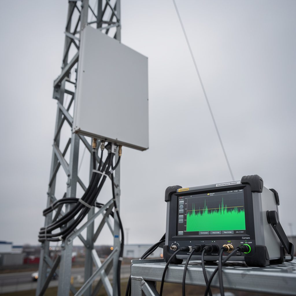
Vertical beamwidth matters just as much for tower-mounted units. A downtilt of even 2 degrees on a rooftop panel antenna can shift the coverage footprint by dozens of meters at street level, which is why mechanical tilt brackets are standard on commercial base station antennas.
Impedance Matching Determines How Much Power Actually Radiates
An antenna is only as good as the match between its feed point and the transmission line. A voltage standing wave ratio (VSWR) of 1.5:1 reflects about 4% of forwarded power back toward the source — tolerable for most links. At 3:1, that reflection climbs past 25%, and the reflected energy can heat up connectors or trip protection circuits in high-power transmitters.
Mismatch doesn't just waste power; it distorts the transmitter's output stage. Power amplifiers designed for a 50-ohm load start behaving unpredictably when the load impedance drifts, producing intermodulation products that show up as interference on adjacent channels. This is why manufacturers specify VSWR across the full operating band, not just at the center frequency.
Matching networks — striplines, baluns, or simple L-networks — get built into the antenna housing precisely to keep this ratio low across temperature swings and mechanical stress from wind loading.
Polarization Alignment Can Make or Break a Link
Two antennas with identical gain and frequency can still fail to communicate if their polarization doesn't line up. A vertically polarized antenna talking to a horizontally polarized one loses roughly 20 dB of signal from cross-polarization discrimination alone — often enough to drop a marginal link entirely.
Circular polarization solves part of this problem for mobile or rotating targets, which is why GPS antennas and many satellite uplinks use it by default. The tradeoff is a few dB of gain compared to a well-aligned linear antenna, accepted because orientation can't always be controlled.
In dense urban deployments, reflected signals off buildings can rotate polarization unpredictably. Engineers sometimes deploy dual-polarized panel antennas specifically to capture both components and let the receiver combine them, recovering signal that a single-polarization design would lose.
Bandwidth and Frequency Response Define Operational Flexibility
An antenna tuned narrowly for 2.4 GHz might show excellent gain and low VSWR at that exact frequency, then degrade sharply just 50 MHz away. This becomes a real problem when a network later adds channels or when regulatory bands get reallocated, as happened with several UHF spectrum reassignments over the past decade.
Wideband designs — log-periodic arrays, discone antennas, broadband helicals — sacrifice some peak gain for a flatter response across a wider frequency range. For a system that needs to support both legacy 900 MHz equipment and newer 2.4 GHz devices on the same tower, a single wideband antenna often costs less than running two narrowband units.
Bandwidth also interacts with physical size. Lower frequencies need larger elements to achieve the same relative bandwidth, which is why a broadband HF antenna for 3–30 MHz coverage can be several meters long, while a comparable UHF design fits in a housing the size of a shoebox.
Environmental and Mechanical Factors Shift the Numbers Over Time
A radome designed to survive ice loading changes the dielectric environment around the antenna element, shifting resonant frequency by a small but measurable amount — sometimes enough to move VSWR from 1.3:1 to 1.8:1 in cold climates. Material choice for reflectors and housings isn't cosmetic; it's part of the RF specification.
Corrosion at connector interfaces raises insertion loss gradually, often going unnoticed until a site survey catches a 2-3 dB drop that wasn't there at commissioning. Specifying marine-grade connectors and gasket seals up front costs less than a service call five years later.
Mounting hardware itself can detune an antenna if it's ferrous and sits too close to the radiating element — a detail that matters when integrators reuse generic brackets across different antenna models instead of the ones specified by the manufacturer.